Template:Installation process
Site preparation requirements
- Find a suitable site on a wall (The mounting surface required to be flat and stable, for example a finished, brick or concrete wall. Wall required to be suitable to withstand TeltoCharge weight with charging cable).
- Make sure that the required power supply is easily accessible. (Required power supply depends on the type of charger).
- Recommendation is not to install TeltoCharge on direct sunlight to avoid overheating.
Installation process
Housing Installation
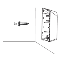
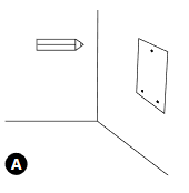 A - Place the drilling template on the wall and mark the three fixing points.
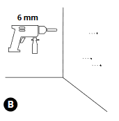 B - Drill holes where the fixing points are marked.
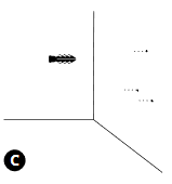 C - Insert the wall plugs into the fixing holes.
1. Fix the device on the wall by inserting the self-tapping screws (start with the top screw and make sure the housing is horizontal).
2. Make sure the cable gland is properly mounted on the cables (AC input cable and Ethernet cable).
Electrical wiring
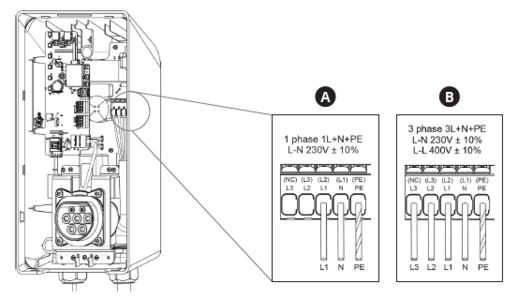
A - T/N single phase set up.
B - T/N Three phase set up.
SIM card installation
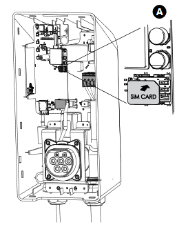
Insert a nano SIM card into card slot.
Closing the middle panel
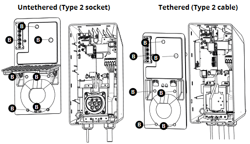
A - Place a middle panel on the housing and press it, till it clicks.
B - Fix it using DIN912 M3x8 screws;
Closing the front plate;
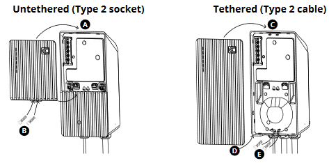
Untethered version
A - Open up bottom part and insert the upper part of the front plate to the fixing holes and fix the plate;
B - Fix it using DIN912 M3x8 screws;
Tethered version
C - Lock the top of the plate;
D - Lock the bottom of the plate;
E - Fix it using DIN912 M3x8 screws;
Disclaimer
RCD - residual current device
Charger shall be installed on power line with RCD Type B. If house grid already has it pre-installed, then additional is not required.
In order to successfully use Teltocharge product, users electrical grid must include dedicated RCD Type B. RCD must be installed by experienced electrician, who installs it parallelly with the charger. Residual current device is not included into the package and have to be bought separately. Legitimate options:
Installation option 1:
Residual current protection (RCBO) type B with tripping current 30 mA and with atleast 32 A overcurrent protection (it is recommended to use 40 A) according to at least one of the standards IEC 61009-1 or IEC 60947-2.
Installation option 2:
Residual current protection (RCCB or RCD) type B with tripping current 30 mA according to at least one of the standards IEC 61008-1 or IEC 61009-1 or IEC 60947-2 or IEC 62423. Additionally overcurrent protection (MCB) rated for atleast 32 A (it is recommended to use 40 A) should be installed and have to be in accordance to at least one of the following standards: IEC 60947-2, IEC 60947-6-2, IEC 61009-1, IEC 60898 series or IEC 60269 series.
Installation option 3:
RCD Type A and appropriate equipment that ensures the disconnection of the supply in case of DC fault current above 6 mA. DC disconnection equipment must meet IEC 62955 standard requirements.
Before buying, please consult with the company, which installs the product.
SPD - surge protection device
In order to successfully use Teltocharge product, users electrical grid must include dedicated Surge Protective Device (SPD in short). SPD must be installed by experienced electrician, who installs charger on the power line with SPD integrated upstream. Firstly, check if house grid already has it pre-installed.
Surge protective device is not included into the package and have to be bought separately. Legitimate options:
Installation option 1:
Surge protective device (SPD) type 1 with max continuous working voltage = 275VAC and maximum transient voltage tolerance of 2500 V. Device must be certified according to the standard IEC 61643 - 11.
Installation option 2:
Surge protective device (SPD) combined type 1&2 with max continuous working voltage = 275VAC and maximum transient voltage tolerance of 2500 V. Device must be certified according to the standard IEC 61643 - 11.
Before buying, please consult with the company, which installs the product.

