Difference between revisions of "Installation process"
m |
m |
||
| Line 1: | Line 1: | ||
| + | ==Site preparation requirements== | ||
| + | * Find a suitable site on a wall (The mounting surface required to be flat and stable, for example a finished, brick or concrete wall. Wall required to be suitable to withstand TeltoCharge weight with charging cable). | ||
| + | * Make sure that the required power supply is easily accessible. (Required power supply depends on the type of charger). | ||
| + | * Make sure that TeltoCharge is not installed on direct sunlight. | ||
==Installation process== | ==Installation process== | ||
===Drilling=== | ===Drilling=== | ||
Revision as of 05:55, 28 March 2022
Main Page > TeltoCharge > Getting Started > Installation processSite preparation requirements
- Find a suitable site on a wall (The mounting surface required to be flat and stable, for example a finished, brick or concrete wall. Wall required to be suitable to withstand TeltoCharge weight with charging cable).
- Make sure that the required power supply is easily accessible. (Required power supply depends on the type of charger).
- Make sure that TeltoCharge is not installed on direct sunlight.
Installation process
Drilling
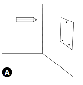 A - Place the drilling template on the wall and mark the three fixing points.
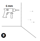 B - Drill holes where the fixing points are marked.
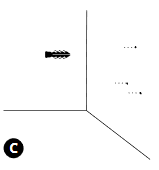 C - Insert the wall plugs into the fixing holes.
Housing Installation
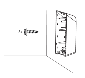
1. Fix the device on the wall by inserting the self-tapping screws (start with the top screw and make sure the housing is horizontal).
2. Make sure the cable grommet is properly mounted on the cables (AC input cable and Ethernet cable).
Electrical wiring
A - T/N single phase set up;
B - T/N Three phase set up;
C - IT/TT three phase set up;
D - IT/TT single phase set up;
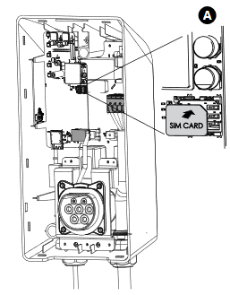
SIM card installation
Insert a nano SIM card into card slot.
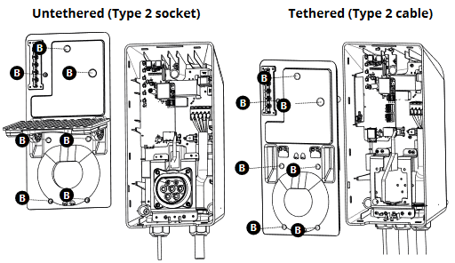
Closing the middle panel
A - Place a middle panel on the housing;
B - Fix it using DIN912 M3x8 screws;
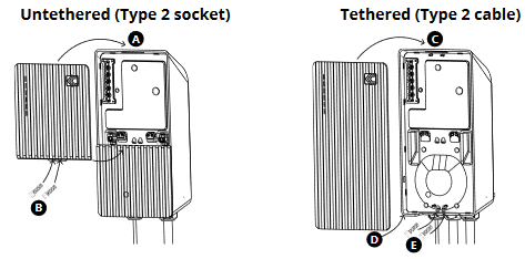
Closing the front plate;
A - Insert the upper part of the front plate to the fixing holes and fix the plate;
B - Fix it using DIN912 M3x8 screws;
C - Lock the top of the plate;
D - Lock the bottom of the plate;
E - Fix it using DIN912 M3x8 screws;
