Difference between revisions of "P1 Modbus Dongle"
| Line 1: | Line 1: | ||
<h1>P1 Modbus Dongle </h1> | <h1>P1 Modbus Dongle </h1> | ||
<p>The Modbus P1 Dongle is a device that enables communication between your TeltoCharge EV charging station and a smart meter using the Modbus RS-485 protocol. This setup is essential for accurately monitoring and controlling the energy usage during EV charging sessions.</p> | <p>The Modbus P1 Dongle is a device that enables communication between your TeltoCharge EV charging station and a smart meter using the Modbus RS-485 protocol. This setup is essential for accurately monitoring and controlling the energy usage during EV charging sessions.</p> | ||
| + | |||
| + | * <p>Accurate energy monitoring: Ensures that energy usage data is correctly captured and transmitted.</p> | ||
| + | * <p>Optimized charging: By leveraging the data from the smart meter, the charging station can optimize the charging process, potentially reducing costs and improving efficiency.</p> | ||
<h2>Smart Meter Connection</h2> | <h2>Smart Meter Connection</h2> | ||
| Line 13: | Line 16: | ||
*Connect the 'B-' terminal of your cable to the 'B-' port on the TeltoCharge device. | *Connect the 'B-' terminal of your cable to the 'B-' port on the TeltoCharge device. | ||
''Note :'' In case of communication errors, swapping the 'A+' and 'B-' connections might resolve the issue. | ''Note :'' In case of communication errors, swapping the 'A+' and 'B-' connections might resolve the issue. | ||
| − | [[File:Modbus p1 dongle -rs485.png|left|frameless]] | + | [[File:Modbus p1 dongle -rs485.png|frameless|alt=|left|400x400px]] |
| + | |||
| + | |||
| + | |||
| + | |||
| + | |||
| + | |||
| + | |||
| + | |||
| + | |||
| + | |||
| + | |||
| + | |||
| + | |||
| + | |||
| + | |||
| + | ===General meter settings=== | ||
| + | According to your smart meter documentation, please enter all the settings into the Teltonika app as shown. | ||
| + | #'''Energy meter type''': You need to select the type of smart meter (1-phase/3-phase). Please note that you can use a 1-phase charger even if the meter is 3-phase. | ||
| + | #'''RS-485 baud rate''': This information can be found in the meter settings accessible through the meter display. If the client cannot locate it, it is recommended to refer to the smart meter manual. | ||
| + | #'''RS-485 parity/stop bit''': Similarly, this information can also be found in the meter settings. If the client is unable to find it, it is advisable to check the smart meter manual. | ||
| + | [[File:Smart meter.app .png|left|alt=|frameless]] | ||
| + | [[File:Live data.png|border|left|frameless|457x457px]] | ||
| + | |||
| + | |||
| + | |||
| + | |||
| + | |||
| + | |||
| + | |||
| + | |||
| + | |||
| + | |||
| + | |||
| + | |||
| + | |||
| + | |||
| + | |||
| + | |||
| + | |||
| + | |||
| + | |||
| + | |||
| + | |||
| + | |||
| + | |||
| + | |||
| + | |||
| + | ''Note :'' After successfully completing these steps, please check the diagnostic live data from the energy meter. | ||
Revision as of 12:42, 2 September 2024
P1 Modbus Dongle
The Modbus P1 Dongle is a device that enables communication between your TeltoCharge EV charging station and a smart meter using the Modbus RS-485 protocol. This setup is essential for accurately monitoring and controlling the energy usage during EV charging sessions.
Accurate energy monitoring: Ensures that energy usage data is correctly captured and transmitted.
Optimized charging: By leveraging the data from the smart meter, the charging station can optimize the charging process, potentially reducing costs and improving efficiency.
Smart Meter Connection
The dongle is connected to the P1 port of the smart meter via a provided P1 cable. This connection allows the dongle to read energy consumption data directly from the smart meter.
RS-485 Connection
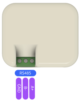
The dongle features RS-485 terminals which are critical for establishing communication with the TeltoCharge system. These terminals are usually labeled as Ground (GND), A+ (positive differential signal), and B- (negative differential signal).
- To connect the dongle to the TeltoCharge, you'll need to use an appropriate RS-485 cable.
- Connect the 'A+' terminal of your cable to the 'A+' port on the TeltoCharge device.
- Connect the 'B-' terminal of your cable to the 'B-' port on the TeltoCharge device.
Note : In case of communication errors, swapping the 'A+' and 'B-' connections might resolve the issue.
General meter settings
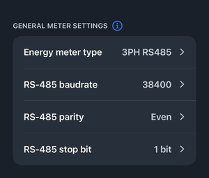
According to your smart meter documentation, please enter all the settings into the Teltonika app as shown.
- Energy meter type: You need to select the type of smart meter (1-phase/3-phase). Please note that you can use a 1-phase charger even if the meter is 3-phase.
- RS-485 baud rate: This information can be found in the meter settings accessible through the meter display. If the client cannot locate it, it is recommended to refer to the smart meter manual.
- RS-485 parity/stop bit: Similarly, this information can also be found in the meter settings. If the client is unable to find it, it is advisable to check the smart meter manual.
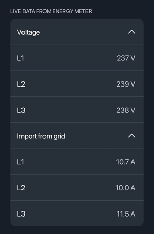
Note : After successfully completing these steps, please check the diagnostic live data from the energy meter.


