Dynamic Load Management EVC16: Difference between revisions
Created page with " = Dynamic Load Management = Dynamic load management is a sophisticated feature that empowers users to efficiently control electric load by managing a group of chargers instal..." |
|||
| (26 intermediate revisions by 2 users not shown) | |||
| Line 6: | Line 6: | ||
Dynamic load management (DLM) is a versatile solution applicable in various scenarios, providing users with the flexibility to choose between using it with or without ct clamps. Here are the key distinctions: | Dynamic load management (DLM) is a versatile solution applicable in various scenarios, providing users with the flexibility to choose between using it with or without ct clamps. Here are the key distinctions: | ||
=== DLM with | === DLM with CT Clamps: === | ||
This configuration is | This configuration is advantageous in the UK, where the use of CT clamps is beneficial for managing the electric load between chargers and other electronic devices. CT clamps enable precise control and optimization of the overall load, contributing to compliance with UK regulations. Their integration into DLM systems assists in efficient energy distribution, which is important for adhering to the energy standards and operational requirements suggested by UK energy authorities. | ||
[[File:Ct clamps.jpg|center|frameless|735x735px]] | |||
== CT Connection == | |||
Dynamic Load Management (DLM) is achieved through a carefully interconnected system of chargers, where communication is governed by a designated "Master" charger, dictating instructions to the remaining "Slave" chargers. These chargers can be interconnected either in a serial or parallel manner, each requiring the use of UTP twisted pair cables for communication via the A and B pins. | |||
[[File:MicrosoftTeams-image (33).png|alt=|frameless|left|[[File:Ct-meter.png|thumb]]]] | |||
[[File:Ct-direction.jpeg|frameless|371x371px|alt=|right]] [[File:Ct-meter.png|frameless|331x331px|alt=|center]] | |||
'''Note :''' The CT cable included in the box is 3 meters long. | |||
* Users can extend it to their desired length, depending on installation conditions such as electrical noise and resistance. | |||
* Recommended extension length is up to 100 meters. | |||
===DLM with smart meter:=== | |||
This configuration enables users to efficiently manage the electric load between chargers and other electronic devices. By leveraging the capabilities of a smart meter, precise control and optimization of the overall load can be achieved. | |||
[[File:DLM with meter.png|center|frameless|800x800px]] | |||
===DLM without external measuring system:=== | |||
In cases where the focus is solely on managing the electricity load between chargers and there are no additional electronic devices contributing to the load, this option can be utilized. It offers a simplified approach to load management, tailored specifically to charger interactions. | |||
[[File:DLM without meter.png|center|frameless|776x776px]] | |||
==Teltonika Energy App Settings== | |||
===General meter settings=== | |||
If you want to enable dynamic load management with a smart meter, it is important to correctly configure the general meter settings. To ensure everything works correctly, please apply the following setup : | |||
* Open user menu | |||
* Open "'''''Installer Menu'''''" | |||
* Open "'''''Load Balancing'''''" menu and select Modbus RTU meter. | |||
* Enable "'''''Load Balancing'''''" | |||
* If smart meter is connected with RS485 wires, press "'''''Search For Device'''''" | |||
* *'''ONLY If TeltoCharge is unable''' to identify energy meter - use "'''''Manual Setup'''''" | |||
[[File:Loadbalancing evc16 meter.png|frameless|764x764px]] | |||
=== General CT settings=== | |||
If you want to enable dynamic load management with a CT, follow the steps below | |||
* Open user menu | |||
* Open "'''''Installer Menu'''''" | |||
* Open "'''''Load Balancing'''''" menu and select CT. | |||
* Enable "'''''Load Balancing'''''" | |||
* Calibrate the CT clamp, it must be connected to the port but not yet clamped around a wire [[File:Loadbalancing evc16 ct.png|frameless|594x594px]] | |||
===Max power from grid=== | |||
It is very important to set ''max power from grid'' parameter correctly in the '''PRIMARY''' charger if you want to use DLM. This parameter shows how much current you have in the circuit you want to balance. That means you have to set all available amperes. | |||
If for example in the Primary charger you will set lower current, DLM might not work correctly and the chargers might not even start the charging process. | |||
For the secondary chargers, this parameter is not as critical. It is advisable to set it to a maximum of 16 A (for 11 kW chargers) or 32 A (for 7.4/22 kW chargers). | |||
[[File:Max_Power.png|alt=Max Power DLM|frameless|458x458px]] | |||
=== Primary Device Configuration === | |||
The first thing would be to select the '''primary''' device that would control the rest of the group communication protocol between the master-slave and master-meter. | |||
It should only be enabled for one charger per group only, the primary charger will handle all the calculations, establish communication with the smart meter and control whole group (maximum group size is 20 devices). | |||
[[File:DLM_primary.png|alt=DLM primary|frameless|856x856px]] | |||
This setting enabled the charger as the primary charger and allows to change the settings that will affect the whole group: | |||
1.'''"Primary device"''' – Confirms that this is the primary device that will control the group | |||
2.'''"Type"''' | |||
* '''Dynamic''' – using a smart meter to balance | |||
* '''Static''' – balancing only from '''''Max power from grid''''' parameter | |||
3.'''"Secondary device count"''' the number of secondary devices | |||
4.'''"Secondary device ID"''' start ID from which chargers will be counted (If it‘s set „2“, the first secondary device must have address 2 and this address must be increased by 1 with each new secondary device | |||
5.'''"Advanced settings" -''' (More info below) | |||
6.'''"Check status"''' – possibility to check communication type with secondary devices | |||
=== Advanced settings === | |||
Advanced settings are the settings that most of the time are left default. Only on special occasions, those settings must be changed. | |||
1. '''"Phase connected"''' – detected automatically | |||
2. '''"Phase sharing mode"''' – type of chargers in group | |||
3. '''"Current sharing mode"''' – Current is distribution mode | |||
* Equal - Energy will be distributed equally among all active chargers | |||
* By Priority - Energy will be distributed based on priority. Chargers will be prioritized according to their '''charging state'''. | |||
4. '''"Communication timeout"''' – delay before warning | |||
5. '''"Communication settings"''' – settings must be the '''same for all the devices in the group''' | |||
* RS-485 baud rate | |||
* RS-485 parity | |||
* RS-485 stop bit | |||
[[File:Advanced_Primary.png|alt=Advanced Primary|frameless|456x456px]] | |||
=== Secondary device configuration === | |||
After Primary device configuration, it’s '''mandatory''' to enable '''Dynamic load management''' mode and correctly set-up '''each secondary device'''. (This action must be repeated for each new secondary device) | |||
For each secondary device few settings must be adjusted: | |||
* '''Max power from grid''' - It is advisable to set it to a maximum of 16 A (for 11 kW chargers) or 32 A (for 7.4/22 kW chargers) | |||
* '''Secondary device''' – enabled | |||
* '''Secondary device ID''' – for the first device it must be as set in the master, for each new secondary device this must be increased by 1 | |||
* '''Advanced settings''' – must match with the primary device settings | |||
[[File:Secondary_config.png|frameless|854x854px]] | |||
Latest revision as of 16:02, 13 March 2026
Dynamic Load Management
Dynamic load management is a sophisticated feature that empowers users to efficiently control electric load by managing a group of chargers installed within a single circuit. Through the implementation of modbus RS-485 communication, the chargers are able to communicate with one another and dynamically adjust their charging power in response to the load on the grid, ensuring optimal charging operations and grid stability.
DLM Types
Dynamic load management (DLM) is a versatile solution applicable in various scenarios, providing users with the flexibility to choose between using it with or without ct clamps. Here are the key distinctions:
DLM with CT Clamps:
This configuration is advantageous in the UK, where the use of CT clamps is beneficial for managing the electric load between chargers and other electronic devices. CT clamps enable precise control and optimization of the overall load, contributing to compliance with UK regulations. Their integration into DLM systems assists in efficient energy distribution, which is important for adhering to the energy standards and operational requirements suggested by UK energy authorities.

CT Connection
Dynamic Load Management (DLM) is achieved through a carefully interconnected system of chargers, where communication is governed by a designated "Master" charger, dictating instructions to the remaining "Slave" chargers. These chargers can be interconnected either in a serial or parallel manner, each requiring the use of UTP twisted pair cables for communication via the A and B pins.
.png)


Note : The CT cable included in the box is 3 meters long.
- Users can extend it to their desired length, depending on installation conditions such as electrical noise and resistance.
- Recommended extension length is up to 100 meters.
DLM with smart meter:
This configuration enables users to efficiently manage the electric load between chargers and other electronic devices. By leveraging the capabilities of a smart meter, precise control and optimization of the overall load can be achieved.

DLM without external measuring system:
In cases where the focus is solely on managing the electricity load between chargers and there are no additional electronic devices contributing to the load, this option can be utilized. It offers a simplified approach to load management, tailored specifically to charger interactions.

Teltonika Energy App Settings
General meter settings
If you want to enable dynamic load management with a smart meter, it is important to correctly configure the general meter settings. To ensure everything works correctly, please apply the following setup :
- Open user menu
- Open "Installer Menu"
- Open "Load Balancing" menu and select Modbus RTU meter.
- Enable "Load Balancing"
- If smart meter is connected with RS485 wires, press "Search For Device"
- *ONLY If TeltoCharge is unable to identify energy meter - use "Manual Setup"

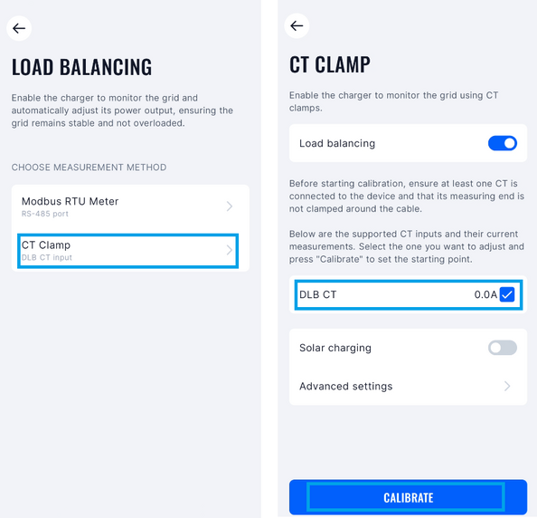
General CT settings
If you want to enable dynamic load management with a CT, follow the steps below
- Open user menu
- Open "Installer Menu"
- Open "Load Balancing" menu and select CT.
- Enable "Load Balancing"
- Calibrate the CT clamp, it must be connected to the port but not yet clamped around a wire

Max power from grid
It is very important to set max power from grid parameter correctly in the PRIMARY charger if you want to use DLM. This parameter shows how much current you have in the circuit you want to balance. That means you have to set all available amperes.
If for example in the Primary charger you will set lower current, DLM might not work correctly and the chargers might not even start the charging process.
For the secondary chargers, this parameter is not as critical. It is advisable to set it to a maximum of 16 A (for 11 kW chargers) or 32 A (for 7.4/22 kW chargers).

Primary Device Configuration
The first thing would be to select the primary device that would control the rest of the group communication protocol between the master-slave and master-meter.
It should only be enabled for one charger per group only, the primary charger will handle all the calculations, establish communication with the smart meter and control whole group (maximum group size is 20 devices).

This setting enabled the charger as the primary charger and allows to change the settings that will affect the whole group:
1."Primary device" – Confirms that this is the primary device that will control the group
2."Type"
- Dynamic – using a smart meter to balance
- Static – balancing only from Max power from grid parameter
3."Secondary device count" the number of secondary devices
4."Secondary device ID" start ID from which chargers will be counted (If it‘s set „2“, the first secondary device must have address 2 and this address must be increased by 1 with each new secondary device
5."Advanced settings" - (More info below)
6."Check status" – possibility to check communication type with secondary devices
Advanced settings
Advanced settings are the settings that most of the time are left default. Only on special occasions, those settings must be changed.
1. "Phase connected" – detected automatically
2. "Phase sharing mode" – type of chargers in group
3. "Current sharing mode" – Current is distribution mode
- Equal - Energy will be distributed equally among all active chargers
- By Priority - Energy will be distributed based on priority. Chargers will be prioritized according to their charging state.
4. "Communication timeout" – delay before warning
5. "Communication settings" – settings must be the same for all the devices in the group
- RS-485 baud rate
- RS-485 parity
- RS-485 stop bit

Secondary device configuration
After Primary device configuration, it’s mandatory to enable Dynamic load management mode and correctly set-up each secondary device. (This action must be repeated for each new secondary device)
For each secondary device few settings must be adjusted:
- Max power from grid - It is advisable to set it to a maximum of 16 A (for 11 kW chargers) or 32 A (for 7.4/22 kW chargers)
- Secondary device – enabled
- Secondary device ID – for the first device it must be as set in the master, for each new secondary device this must be increased by 1
- Advanced settings – must match with the primary device settings
