Difference between revisions of "P1 Modbus Dongle"
| (28 intermediate revisions by the same user not shown) | |||
| Line 1: | Line 1: | ||
| − | <h1> | + | <h1>P1 Modbus Dongle </h1> |
<p>The Modbus P1 Dongle is a device that enables communication between your TeltoCharge EV charging station and a smart meter using the Modbus RS-485 protocol. This setup is essential for accurately monitoring and controlling the energy usage during EV charging sessions.</p> | <p>The Modbus P1 Dongle is a device that enables communication between your TeltoCharge EV charging station and a smart meter using the Modbus RS-485 protocol. This setup is essential for accurately monitoring and controlling the energy usage during EV charging sessions.</p> | ||
| − | + | <h2>Smart Meter Connection</h2> | |
| − | + | <p>The dongle is connected to the P1 port of the smart meter via a provided P1 cable. This connection allows the dongle to read energy consumption data directly from the smart meter.</p> | |
| − | + | ||
| − | <p>The dongle is connected to the P1 port of the smart meter via a provided P1 cable. This connection allows the dongle to read energy consumption data directly from the smart meter.</p>'''RS-485 Connection''' | + | '''RS-485 Connection''' |
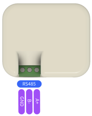
The dongle features RS-485 terminals which are critical for establishing communication with the TeltoCharge system. These terminals are usually labeled as Ground (GND), A+ (positive differential signal), and B- (negative differential signal). | The dongle features RS-485 terminals which are critical for establishing communication with the TeltoCharge system. These terminals are usually labeled as Ground (GND), A+ (positive differential signal), and B- (negative differential signal). | ||
| − | *To connect the dongle to the TeltoCharge, you'll need to use an appropriate RS-485 cable. | + | *To connect the dongle to the TeltoCharge system, you'll need to use an appropriate RS-485 cable. |
*Connect the 'A+' terminal of your cable to the 'A+' port on the TeltoCharge device. | *Connect the 'A+' terminal of your cable to the 'A+' port on the TeltoCharge device. | ||
*Connect the 'B-' terminal of your cable to the 'B-' port on the TeltoCharge device. | *Connect the 'B-' terminal of your cable to the 'B-' port on the TeltoCharge device. | ||
''Note :'' In case of communication errors, swapping the 'A+' and 'B-' connections might resolve the issue. | ''Note :'' In case of communication errors, swapping the 'A+' and 'B-' connections might resolve the issue. | ||
| − | [[File:Modbus p1 dongle -rs485 | + | [[File:Modbus p1 dongle -rs485.png|left|frameless]] |
| − | |||
| − | |||
| − | |||
| − | |||
| − | |||
| − | |||
| − | |||
| − | |||
| − | |||
| − | |||
| − | |||
| − | |||
| − | |||
| − | |||
| − | |||
| − | |||
| − | |||
| − | |||
| − | |||
| − | |||
| − | |||
| − | |||
| − | |||
| − | |||
| − | |||
| − | |||
| − | |||
| − | |||
| − | |||
| − | |||
| − | |||
| − | |||
| − | |||
| − | |||
| − | |||
| − | |||
| − | |||
| − | |||
| − | |||
| − | |||
| − | |||
| − | |||
| − | |||
| − | |||
| − | |||
| − | |||
| − | |||
| − | |||
| − | |||
| − | |||
| − | |||
| − | |||
| − | |||
| − | |||
| − | |||
| − | |||
| − | |||
| − | |||
| − | |||
| − | |||
| − | |||
| − | |||
Revision as of 08:21, 2 September 2024
P1 Modbus Dongle
The Modbus P1 Dongle is a device that enables communication between your TeltoCharge EV charging station and a smart meter using the Modbus RS-485 protocol. This setup is essential for accurately monitoring and controlling the energy usage during EV charging sessions.
Smart Meter Connection
The dongle is connected to the P1 port of the smart meter via a provided P1 cable. This connection allows the dongle to read energy consumption data directly from the smart meter.
RS-485 Connection
The dongle features RS-485 terminals which are critical for establishing communication with the TeltoCharge system. These terminals are usually labeled as Ground (GND), A+ (positive differential signal), and B- (negative differential signal).
- To connect the dongle to the TeltoCharge system, you'll need to use an appropriate RS-485 cable.
- Connect the 'A+' terminal of your cable to the 'A+' port on the TeltoCharge device.
- Connect the 'B-' terminal of your cable to the 'B-' port on the TeltoCharge device.
Note : In case of communication errors, swapping the 'A+' and 'B-' connections might resolve the issue.
