Difference between revisions of "Dynamic Load Management EVC16"
| (19 intermediate revisions by 2 users not shown) | |||
| Line 7: | Line 7: | ||
=== DLM with Ct Clamps: === | === DLM with Ct Clamps: === | ||
| − | This configuration is | + | This configuration is advantageous in the UK, where the use of CT clamps is beneficial for managing the electric load between chargers and other electronic devices. CT clamps enable precise control and optimization of the overall load, contributing to compliance with UK regulations. Their integration into DLM systems assists in efficient energy distribution, which is important for adhering to the energy standards and operational requirements suggested by UK energy authorities. |
[[File:Ct clamps.jpg|center|frameless|735x735px]] | [[File:Ct clamps.jpg|center|frameless|735x735px]] | ||
== CT Connection == | == CT Connection == | ||
Dynamic Load Management (DLM) is achieved through a carefully interconnected system of chargers, where communication is governed by a designated "Master" charger, dictating instructions to the remaining "Slave" chargers. These chargers can be interconnected either in a serial or parallel manner, each requiring the use of UTP twisted pair cables for communication via the A and B pins. | Dynamic Load Management (DLM) is achieved through a carefully interconnected system of chargers, where communication is governed by a designated "Master" charger, dictating instructions to the remaining "Slave" chargers. These chargers can be interconnected either in a serial or parallel manner, each requiring the use of UTP twisted pair cables for communication via the A and B pins. | ||
| − | |||
| − | |||
| − | === DLM with smart meter: === | + | [[File:MicrosoftTeams-image (33).png|alt=|frameless|left|[[File:Ct-meter.png|thumb]]]] |
| + | [[File:Ct-direction.jpeg|frameless|371x371px|alt=|right]] [[File:Ct-meter.png|frameless|331x331px|alt=|center]] | ||
| + | '''Note :''' The CT cable included in the box is 3 meters long. | ||
| + | * Users can extend it to their desired length, depending on installation conditions such as electrical noise and resistance. | ||
| + | * Recommended extension length is up to 100 meters. | ||
| + | |||
| + | ===DLM with smart meter:=== | ||
This configuration enables users to efficiently manage the electric load between chargers and other electronic devices. By leveraging the capabilities of a smart meter, precise control and optimization of the overall load can be achieved. | This configuration enables users to efficiently manage the electric load between chargers and other electronic devices. By leveraging the capabilities of a smart meter, precise control and optimization of the overall load can be achieved. | ||
| Line 21: | Line 25: | ||
| − | + | ===DLM without external measuring system:=== | |
| − | === DLM without external measuring system: === | ||
In cases where the focus is solely on managing the electricity load between chargers and there are no additional electronic devices contributing to the load, this option can be utilized. It offers a simplified approach to load management, tailored specifically to charger interactions. | In cases where the focus is solely on managing the electricity load between chargers and there are no additional electronic devices contributing to the load, this option can be utilized. It offers a simplified approach to load management, tailored specifically to charger interactions. | ||
| Line 28: | Line 31: | ||
[[File:DLM without meter.png|center|frameless|776x776px]] | [[File:DLM without meter.png|center|frameless|776x776px]] | ||
| − | == Teltonika Energy App Settings == | + | ==Teltonika Energy App Settings== |
Once the chargers are properly connected to the electrical grid and interconnected to each other, the next step is to configure the settings for each charger using the Teltonika Energy app. Below, you will find a comprehensive list of the settings that should be adjusted to achieve DLM functionality. | Once the chargers are properly connected to the electrical grid and interconnected to each other, the next step is to configure the settings for each charger using the Teltonika Energy app. Below, you will find a comprehensive list of the settings that should be adjusted to achieve DLM functionality. | ||
| − | === Max power from grid === | + | ===Max power from grid=== |
| + | [[File:2023-07-03 07 42 32-Window.png|right|frameless|245x245px]] | ||
It is very important to set this parameter correctly in the master charger if you want to use DLM. This parameter shows how much of current you have in the circuit you want to balance. That means you have to set as much as this current can have amperes. Usually it should be the same current as the breaker tripping current. If for example in the master charger you will set lower current, DLM might not work and charger might not even start charging process. | It is very important to set this parameter correctly in the master charger if you want to use DLM. This parameter shows how much of current you have in the circuit you want to balance. That means you have to set as much as this current can have amperes. Usually it should be the same current as the breaker tripping current. If for example in the master charger you will set lower current, DLM might not work and charger might not even start charging process. | ||
For the slave charger, this parameter is not as critical. It is advisable to set it to a maximum of 16 A (for 11 kW chargers) or 32 A (for 7.4/22 kW chargers). | For the slave charger, this parameter is not as critical. It is advisable to set it to a maximum of 16 A (for 11 kW chargers) or 32 A (for 7.4/22 kW chargers). | ||
| + | |||
| + | |||
| + | ===General meter settings=== | ||
| + | If you want to enable dynamic load management with a smart meter, it is important to correctly configure the general meter settings. | ||
| + | [[File:2023-07-03 07 45 16-Window.png|right|frameless|264x264px]] | ||
| + | |||
| + | #'''Energy meter type''': You need to select the type of smart meter (1-phase/3-phase). Please note that you can use a 1-phase charger even if the meter is 3-phase. | ||
| + | #'''RS-485 baud rate''': This information can be found in the meter settings accessible through the meter display. If the client cannot locate it, it is recommended to refer to the smart meter manual. | ||
| + | #'''RS-485 parity/stop bit''': Similarly, this information can also be found in the meter settings. If the client is unable to find it, it is advisable to check the smart meter manual. | ||
| + | |||
| + | These settings must be configured for all chargers in the circuit, regardless of whether they are slaves and have direct communication with the meter. These settings establish the communication protocol between the master-slave and master-meter. | ||
| + | |||
| + | === General CT settings=== | ||
| + | [[File:Calibrate-ct.jpg|right|frameless|266x266px|link=Special:FilePath/Calibrate-ct.jpg]] | ||
| + | 1- By default, it is set to 3 seconds. However, there may be cases where the user needs to increase this value. For instance, if there are significant distances between the chargers and the ct clamps or if there are numerous interconnected chargers. | ||
| + | #'''Measuring device''': The meter should be selected. For UK chargers, it is possible to choose CT clamps | ||
| + | #'''Energy meter address''': This information can be found in the meter settings accessed through the meter display. | ||
| + | Note: Before calibration, CT have to be connected to the port, but not clamped around the cable. | ||
| + | |||
| + | ===How to calibrate CT:=== | ||
| + | |||
| + | 1- Before calibration, CT have to be connected to the port, but not clamped around the cable. | ||
| + | |||
| + | 2- Check DLB CT and press Calibrate. | ||
| + | [[File:App-ct-configuration.jpg|right|frameless|245x245px]] | ||
| + | 3 - Success. | ||
| + | |||
| + | ===Dynamic Load Balancing=== | ||
| + | To access the DLM functionality, the user must first enable the DLB functionality | ||
| + | |||
| + | #'''Measuring device''': The meter should be selected. For UK chargers, it is possible to choose CT clamps. | ||
| + | #'''Energy meter address''': This information can be found in the meter settings accessed through the meter display. If the address cannot be located, it is recommended to consult the smart meter manual. | ||
| + | #'''Current update interval''': By default, it is set to 3 seconds. However, there may be cases where the user needs to increase this value. For instance, if there are significant distances between the chargers and the smart meter or if there are numerous interconnected chargers. | ||
| + | |||
| + | ===Dynamic Load Management=== | ||
| + | When setting up all the previous configurations, it is time to proceed with the main DLM settings. To enable these settings, the user must first activate DLM. | ||
| + | [[File:Dlm.png|right|frameless|292x292px]] | ||
| + | #'''Master mode''': This setting designates the charger as the master charger. It should only be enabled for one charger, which will handle all the calculations and establish communication with the smart meter. | ||
| + | #'''Measure grid load''': This setting should be enabled if DLM functionality with a meter is desired. If there are no plans to use a smart meter, it is important to disable this setting to prevent meter errors due to lack of connection. Please note that this setting is exclusively available for the master charger | ||
| + | #'''Current sharing mode''' - There are two distinct current sharing modes available: | ||
| + | #*Equal distribution: Energy will be distributed equally among all active chargers. | ||
| + | #*Distribution by priority: Energy will be distributed based on priority. Chargers will be prioritized according to their charging state, and those with higher priority will receive maximum charging power.[[File:Dlm.png|right|frameless|276x276px]]''For example, if we have a 100 A grid and five connected chargers, each capable of accepting 30 A, the first three chargers will receive 30 A each. The fourth charger will receive only 10 A, and the fifth charger will not initiate the charging process at all. This setting is exclusive to the master charger.'' | ||
| + | #'''Slave Modbus address start''' - This setting is exclusive to the master charger. The user needs to specify the starting address for the slave chargers. For instance, if the start address is set to 1, the first slave charger should have address 1, the second should have address 2, the third should have address 3, and so on. | ||
| + | #Each slave charger has its own specific setting called "'''Slave Modbus address'''". This setting must be configured individually for each charger. | ||
| + | #'''Number of devices''' - This setting is available only for the master charger. The administrator must specify the total number of slave chargers that will be connected in the circuit. | ||
Latest revision as of 09:25, 7 August 2024
Pages with broken file links > Dynamic Load Management EVC16Dynamic Load Management
Dynamic load management is a sophisticated feature that empowers users to efficiently control electric load by managing a group of chargers installed within a single circuit. Through the implementation of modbus RS-485 communication, the chargers are able to communicate with one another and dynamically adjust their charging power in response to the load on the grid, ensuring optimal charging operations and grid stability.
DLM Types
Dynamic load management (DLM) is a versatile solution applicable in various scenarios, providing users with the flexibility to choose between using it with or without ct clamps. Here are the key distinctions:
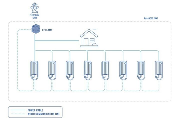
DLM with Ct Clamps:
This configuration is advantageous in the UK, where the use of CT clamps is beneficial for managing the electric load between chargers and other electronic devices. CT clamps enable precise control and optimization of the overall load, contributing to compliance with UK regulations. Their integration into DLM systems assists in efficient energy distribution, which is important for adhering to the energy standards and operational requirements suggested by UK energy authorities.
CT Connection
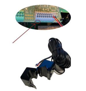
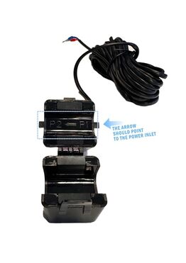
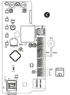
Dynamic Load Management (DLM) is achieved through a carefully interconnected system of chargers, where communication is governed by a designated "Master" charger, dictating instructions to the remaining "Slave" chargers. These chargers can be interconnected either in a serial or parallel manner, each requiring the use of UTP twisted pair cables for communication via the A and B pins.
Note : The CT cable included in the box is 3 meters long.
- Users can extend it to their desired length, depending on installation conditions such as electrical noise and resistance.
- Recommended extension length is up to 100 meters.
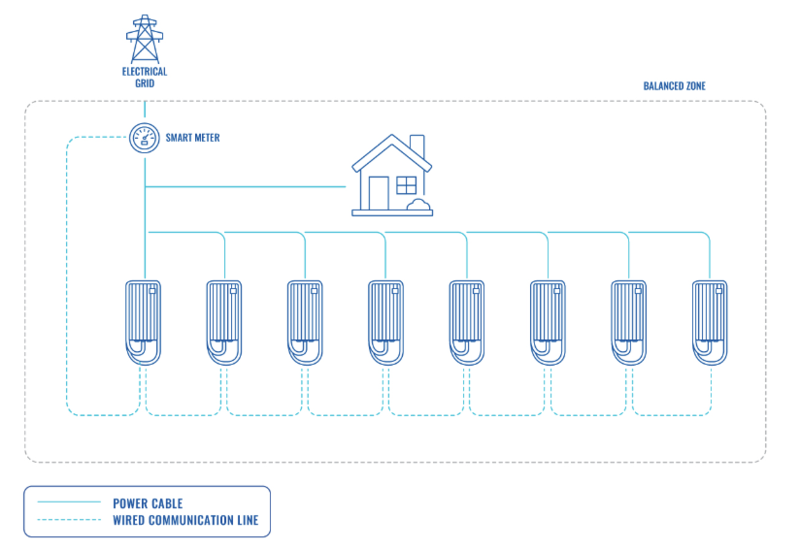
DLM with smart meter:
This configuration enables users to efficiently manage the electric load between chargers and other electronic devices. By leveraging the capabilities of a smart meter, precise control and optimization of the overall load can be achieved.
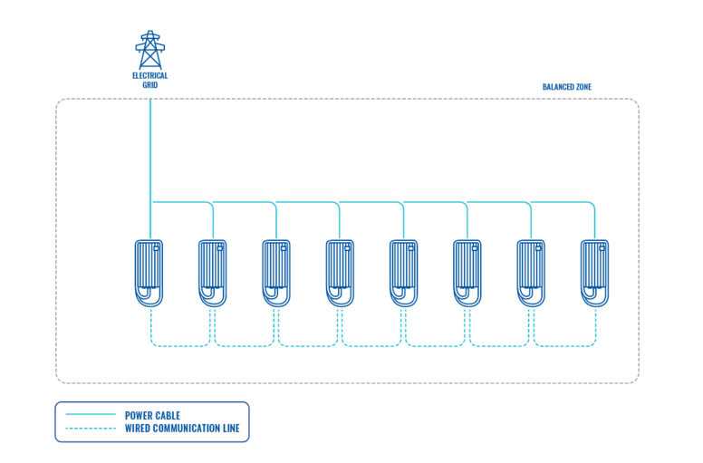
DLM without external measuring system:
In cases where the focus is solely on managing the electricity load between chargers and there are no additional electronic devices contributing to the load, this option can be utilized. It offers a simplified approach to load management, tailored specifically to charger interactions.
Teltonika Energy App Settings
Once the chargers are properly connected to the electrical grid and interconnected to each other, the next step is to configure the settings for each charger using the Teltonika Energy app. Below, you will find a comprehensive list of the settings that should be adjusted to achieve DLM functionality.
Max power from grid
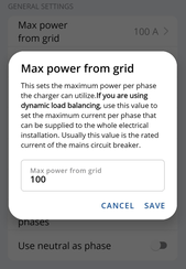
It is very important to set this parameter correctly in the master charger if you want to use DLM. This parameter shows how much of current you have in the circuit you want to balance. That means you have to set as much as this current can have amperes. Usually it should be the same current as the breaker tripping current. If for example in the master charger you will set lower current, DLM might not work and charger might not even start charging process.
For the slave charger, this parameter is not as critical. It is advisable to set it to a maximum of 16 A (for 11 kW chargers) or 32 A (for 7.4/22 kW chargers).
General meter settings
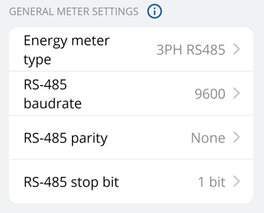
If you want to enable dynamic load management with a smart meter, it is important to correctly configure the general meter settings.
- Energy meter type: You need to select the type of smart meter (1-phase/3-phase). Please note that you can use a 1-phase charger even if the meter is 3-phase.
- RS-485 baud rate: This information can be found in the meter settings accessible through the meter display. If the client cannot locate it, it is recommended to refer to the smart meter manual.
- RS-485 parity/stop bit: Similarly, this information can also be found in the meter settings. If the client is unable to find it, it is advisable to check the smart meter manual.
These settings must be configured for all chargers in the circuit, regardless of whether they are slaves and have direct communication with the meter. These settings establish the communication protocol between the master-slave and master-meter.
General CT settings
1- By default, it is set to 3 seconds. However, there may be cases where the user needs to increase this value. For instance, if there are significant distances between the chargers and the ct clamps or if there are numerous interconnected chargers.
- Measuring device: The meter should be selected. For UK chargers, it is possible to choose CT clamps
- Energy meter address: This information can be found in the meter settings accessed through the meter display.
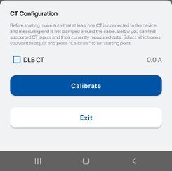
Note: Before calibration, CT have to be connected to the port, but not clamped around the cable.
How to calibrate CT:
1- Before calibration, CT have to be connected to the port, but not clamped around the cable.
2- Check DLB CT and press Calibrate.
3 - Success.
Dynamic Load Balancing
To access the DLM functionality, the user must first enable the DLB functionality
- Measuring device: The meter should be selected. For UK chargers, it is possible to choose CT clamps.
- Energy meter address: This information can be found in the meter settings accessed through the meter display. If the address cannot be located, it is recommended to consult the smart meter manual.
- Current update interval: By default, it is set to 3 seconds. However, there may be cases where the user needs to increase this value. For instance, if there are significant distances between the chargers and the smart meter or if there are numerous interconnected chargers.
Dynamic Load Management
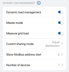
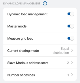
When setting up all the previous configurations, it is time to proceed with the main DLM settings. To enable these settings, the user must first activate DLM.
- Master mode: This setting designates the charger as the master charger. It should only be enabled for one charger, which will handle all the calculations and establish communication with the smart meter.
- Measure grid load: This setting should be enabled if DLM functionality with a meter is desired. If there are no plans to use a smart meter, it is important to disable this setting to prevent meter errors due to lack of connection. Please note that this setting is exclusively available for the master charger
- Current sharing mode - There are two distinct current sharing modes available:
- Equal distribution: Energy will be distributed equally among all active chargers.
- Distribution by priority: Energy will be distributed based on priority. Chargers will be prioritized according to their charging state, and those with higher priority will receive maximum charging power.For example, if we have a 100 A grid and five connected chargers, each capable of accepting 30 A, the first three chargers will receive 30 A each. The fourth charger will receive only 10 A, and the fifth charger will not initiate the charging process at all. This setting is exclusive to the master charger.
- Slave Modbus address start - This setting is exclusive to the master charger. The user needs to specify the starting address for the slave chargers. For instance, if the start address is set to 1, the first slave charger should have address 1, the second should have address 2, the third should have address 3, and so on.
- Each slave charger has its own specific setting called "Slave Modbus address". This setting must be configured individually for each charger.
- Number of devices - This setting is available only for the master charger. The administrator must specify the total number of slave chargers that will be connected in the circuit.
