Difference between revisions of "Dynamic Load Management EVC16"
| (14 intermediate revisions by 2 users not shown) | |||
| Line 7: | Line 7: | ||
=== DLM with Ct Clamps: === | === DLM with Ct Clamps: === | ||
| − | This configuration is | + | This configuration is essential in the UK, where the use of CT clamps is mandatory for managing the electric load between chargers and other electronic devices. CT clamps facilitate compliance with UK regulations by enabling precise control and optimization of the overall load. Their integration into DLM systems ensures efficient energy distribution, essential for meeting the stringent energy standards and operational requirements set forth by UK energy authorities. |
[[File:Ct clamps.jpg|center|frameless|735x735px]] | [[File:Ct clamps.jpg|center|frameless|735x735px]] | ||
== CT Connection == | == CT Connection == | ||
| Line 13: | Line 13: | ||
| − | [[File:MicrosoftTeams-image (33).png|alt=|frameless|left | + | [[File:MicrosoftTeams-image (33).png|alt=|frameless|left]] |
| − | + | [[File:Ct-meter.png|center|frameless|349x349px]] | |
| − | |||
| − | |||
| − | |||
| − | ===DLM with smart meter:=== | + | === DLM with smart meter: === |
This configuration enables users to efficiently manage the electric load between chargers and other electronic devices. By leveraging the capabilities of a smart meter, precise control and optimization of the overall load can be achieved. | This configuration enables users to efficiently manage the electric load between chargers and other electronic devices. By leveraging the capabilities of a smart meter, precise control and optimization of the overall load can be achieved. | ||
| Line 25: | Line 22: | ||
| − | ===DLM without external measuring system:=== | + | |
| + | === DLM without external measuring system: === | ||
In cases where the focus is solely on managing the electricity load between chargers and there are no additional electronic devices contributing to the load, this option can be utilized. It offers a simplified approach to load management, tailored specifically to charger interactions. | In cases where the focus is solely on managing the electricity load between chargers and there are no additional electronic devices contributing to the load, this option can be utilized. It offers a simplified approach to load management, tailored specifically to charger interactions. | ||
| Line 31: | Line 29: | ||
[[File:DLM without meter.png|center|frameless|776x776px]] | [[File:DLM without meter.png|center|frameless|776x776px]] | ||
| − | ==Teltonika Energy App Settings== | + | == Teltonika Energy App Settings == |
Once the chargers are properly connected to the electrical grid and interconnected to each other, the next step is to configure the settings for each charger using the Teltonika Energy app. Below, you will find a comprehensive list of the settings that should be adjusted to achieve DLM functionality. | Once the chargers are properly connected to the electrical grid and interconnected to each other, the next step is to configure the settings for each charger using the Teltonika Energy app. Below, you will find a comprehensive list of the settings that should be adjusted to achieve DLM functionality. | ||
| − | ===Max power from grid=== | + | === Max power from grid === |
| − | |||
It is very important to set this parameter correctly in the master charger if you want to use DLM. This parameter shows how much of current you have in the circuit you want to balance. That means you have to set as much as this current can have amperes. Usually it should be the same current as the breaker tripping current. If for example in the master charger you will set lower current, DLM might not work and charger might not even start charging process. | It is very important to set this parameter correctly in the master charger if you want to use DLM. This parameter shows how much of current you have in the circuit you want to balance. That means you have to set as much as this current can have amperes. Usually it should be the same current as the breaker tripping current. If for example in the master charger you will set lower current, DLM might not work and charger might not even start charging process. | ||
For the slave charger, this parameter is not as critical. It is advisable to set it to a maximum of 16 A (for 11 kW chargers) or 32 A (for 7.4/22 kW chargers). | For the slave charger, this parameter is not as critical. It is advisable to set it to a maximum of 16 A (for 11 kW chargers) or 32 A (for 7.4/22 kW chargers). | ||
| + | === General CT settings === | ||
| + | [[File:Ctapp.png|right|frameless|498x498px]] | ||
| + | 1- We have to choose Current update interval – how often current measurement have to be updated. By default it is 3 s. | ||
| − | + | 2- We can calibrate our DLB CT clamp to set starting point. | |
| − | |||
| − | |||
| − | |||
| − | |||
| − | |||
| − | |||
| − | |||
| − | |||
| − | |||
| − | |||
| − | |||
| − | |||
| − | |||
| − | |||
| − | |||
| − | |||
| − | |||
| − | |||
| − | |||
| − | |||
| − | |||
| − | |||
| − | |||
| − | |||
| − | |||
| − | |||
| − | |||
| − | |||
| − | |||
| − | |||
| − | + | Note: before calibration, CT have to be connected to the port, but not clamped around the cable. | |
| − | |||
| − | |||
| − | |||
| − | |||
| − | |||
| − | |||
| − | |||
| − | |||
| − | |||
| − | |||
Revision as of 07:31, 27 February 2024
Pages with broken file links > Dynamic Load Management EVC16Dynamic Load Management
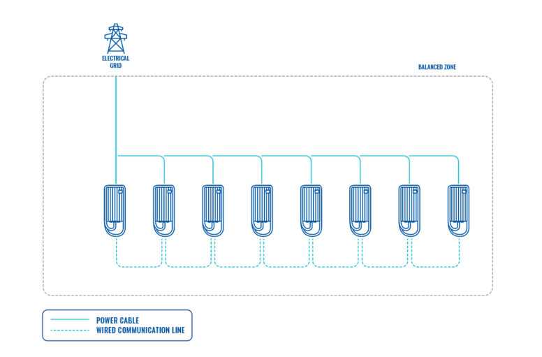
Dynamic load management is a sophisticated feature that empowers users to efficiently control electric load by managing a group of chargers installed within a single circuit. Through the implementation of modbus RS-485 communication, the chargers are able to communicate with one another and dynamically adjust their charging power in response to the load on the grid, ensuring optimal charging operations and grid stability.
DLM Types
Dynamic load management (DLM) is a versatile solution applicable in various scenarios, providing users with the flexibility to choose between using it with or without ct clamps. Here are the key distinctions:
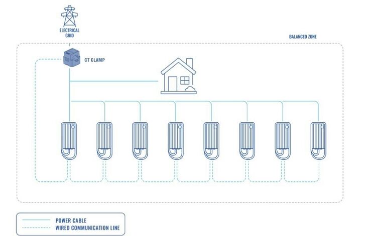
DLM with Ct Clamps:
This configuration is essential in the UK, where the use of CT clamps is mandatory for managing the electric load between chargers and other electronic devices. CT clamps facilitate compliance with UK regulations by enabling precise control and optimization of the overall load. Their integration into DLM systems ensures efficient energy distribution, essential for meeting the stringent energy standards and operational requirements set forth by UK energy authorities.
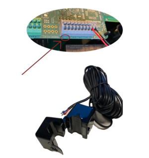
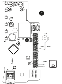
CT Connection
Dynamic Load Management (DLM) is achieved through a carefully interconnected system of chargers, where communication is governed by a designated "Master" charger, dictating instructions to the remaining "Slave" chargers. These chargers can be interconnected either in a serial or parallel manner, each requiring the use of UTP twisted pair cables for communication via the A and B pins.
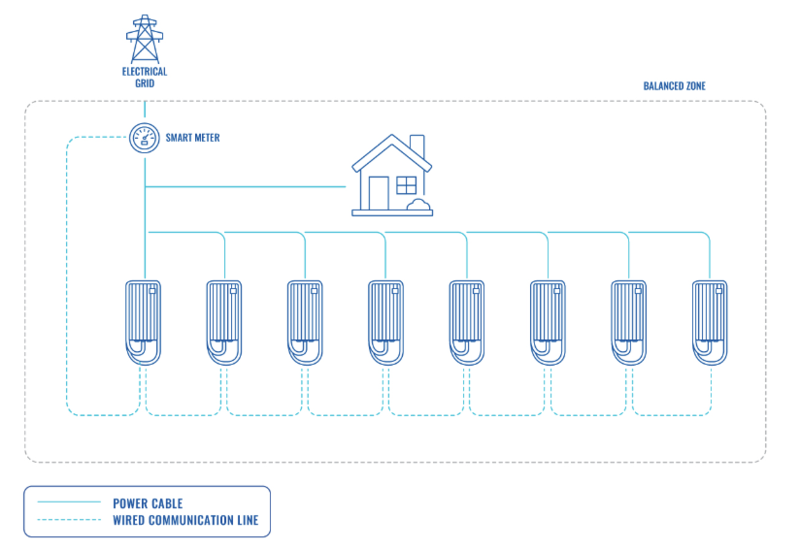
DLM with smart meter:
This configuration enables users to efficiently manage the electric load between chargers and other electronic devices. By leveraging the capabilities of a smart meter, precise control and optimization of the overall load can be achieved.
DLM without external measuring system:
In cases where the focus is solely on managing the electricity load between chargers and there are no additional electronic devices contributing to the load, this option can be utilized. It offers a simplified approach to load management, tailored specifically to charger interactions.
Teltonika Energy App Settings
Once the chargers are properly connected to the electrical grid and interconnected to each other, the next step is to configure the settings for each charger using the Teltonika Energy app. Below, you will find a comprehensive list of the settings that should be adjusted to achieve DLM functionality.
Max power from grid
It is very important to set this parameter correctly in the master charger if you want to use DLM. This parameter shows how much of current you have in the circuit you want to balance. That means you have to set as much as this current can have amperes. Usually it should be the same current as the breaker tripping current. If for example in the master charger you will set lower current, DLM might not work and charger might not even start charging process.
For the slave charger, this parameter is not as critical. It is advisable to set it to a maximum of 16 A (for 11 kW chargers) or 32 A (for 7.4/22 kW chargers).
General CT settings
1- We have to choose Current update interval – how often current measurement have to be updated. By default it is 3 s.
2- We can calibrate our DLB CT clamp to set starting point.
Note: before calibration, CT have to be connected to the port, but not clamped around the cable.
